
In this electronics project, I will demonstrate how to make a high-efficiency LED flashlight capable of driving the 10 LEDs with a 1.2 V or 1.5 V single cell.
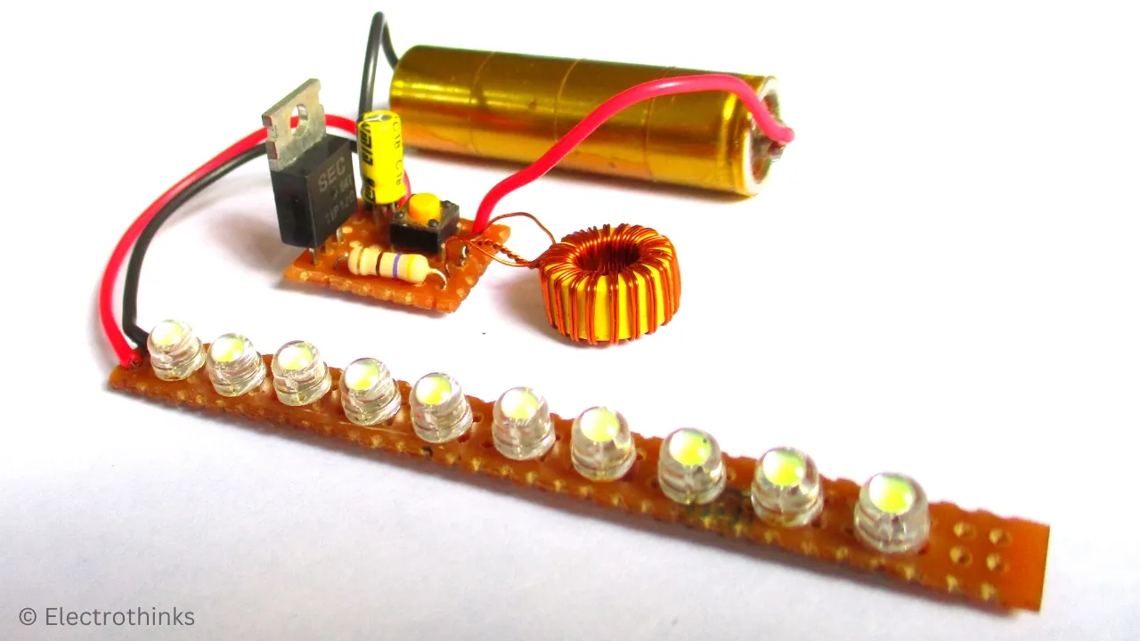
This flashlight is designed to work continuously for 3 to 6 hours, ensuring reliable long-term operation even in sub-zero temperatures.
Let's make it!
Components for LED Flashlight
The following components are required to make this flashlight circuit:
| Name | Value | Qty. |
|---|---|---|
| D1 to D10: White LED | 4.8 MM, 3.2-3.4 V @ 20mA | 10 |
| Q1: NPN Power Darlington Transistor | TIP120 | 1 |
| R1: Resistor | 470Ω, 1/4W | 1 |
| D11: Schottky Diode | SK24 | 1 |
| C1: Electrolytic Capacitor | 10uF, 35V | 1 |
| B1: Single Cell | 1.2 V Ni-Cd/Ni-Mh AA or 1.5 V AA | 1 |
| SW1: Switch | Push Button | 1 |
| T1: Magnetic Ferrite Core | Small Size Toroid | 1 |
| Insulated Copper Coil | 0.2 - 0.4 MM | 1 |
| Veroboard | 85MM x 7MM & 20MM x 20MM (W x L) | 2 |
| Connecting Wire | - | - |
| Soldering Iron Kit | - | - |
10 LED Flashlight Circuit Diagram
Schematic of the 10 LED flashlight circuit for single cell is shown below.

After Soldering LED Flashlight Circuit
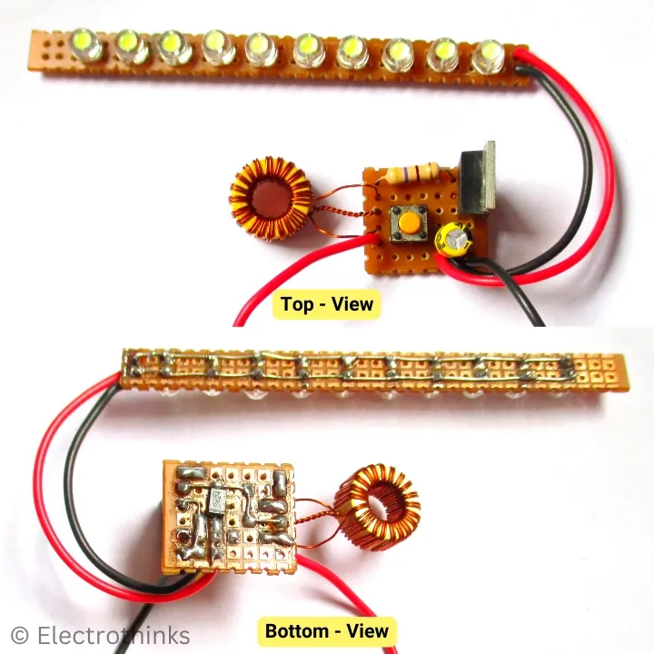
I arranged the components and soldered the LED panel circuit and LED driver circuit separately onto a Veroboard following the schematic. Here, you can see the complete circuit board after the soldering.
Demo & Testing - 10 LED Flashlight with Single Cell
This high-efficiency LED driver circuit can drive up to 10 LEDs and starts working at an input voltage of 0.4 Volts. It consumes approximately 80-90 milliampere from 1.2 Volts onwards. The correct operating voltage range is up to 3.5 Volts.
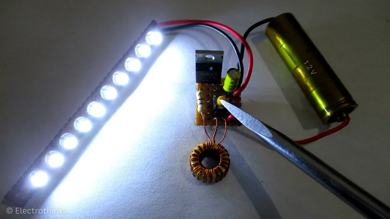
To testing the circuit, I just connect a 1.2 V Ni-Cd AA cell to the circuit board and press the push button. Here, you can see the super high brightness of this LED flashlight.


0 Comments: