
In this electronics project, I will demonstrate how to make a high-efficiency LED flashlight capable of driving the 10 LEDs with a 1.2 V or 1.5 V single cell.
This flashlight is designed to work continuously for 3 to 6 hours, ensuring reliable long-term operation even in sub-zero temperatures.
Let's make it!
Components for LED Flashlight
The following components are required to make this flashlight circuit:
| Name | Value | Qty. |
|---|---|---|
| D1 to D10: White LED | 4.8 MM, 3.2-3.4 V @ 20mA | 10 |
| Q1: NPN Power Darlington Transistor | TIP120 | 1 |
| R1: Resistor | 470Ω, 1/4W | 1 |
| D11: Schottky Diode | SK24 | 1 |
| C1: Electrolytic Capacitor | 10uF, 35V | 1 |
| B1: Single Cell | 1.2 V Ni-Cd/Ni-Mh AA or 1.5 V AA | 1 |
| SW1: Switch | Push Button | 1 |
| T1: Magnetic Ferrite Core | Small Size Toroid | 1 |
| Insulated Copper Coil | 0.2 - 0.4 MM | 1 |
| Veroboard | 85MM x 7MM & 20MM x 20MM (W x L) | 2 |
| Connecting Wire | - | - |
| Soldering Iron Kit | - | - |
10 LED Flashlight Circuit Diagram
Schematic of the 10 LED flashlight circuit for single cell is shown below.

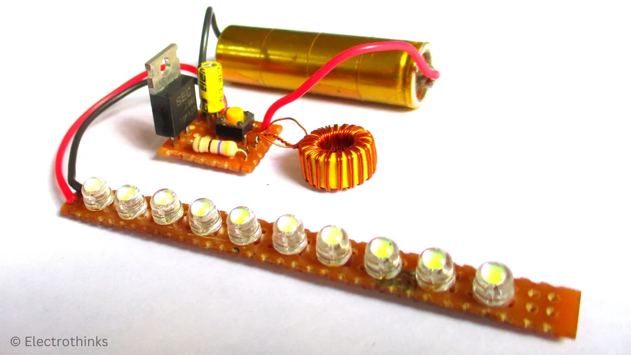
After Soldering LED Flashlight Circuit
I arranged the components and soldered the LED panel circuit and LED driver circuit separately onto a Veroboard following the schematic. Here, you can see the complete circuit board after the soldering.

Demo & Testing - 10 LED Flashlight with Single Cell
This high-efficiency LED driver circuit can drive up to 10 LEDs and starts working at an input voltage of 0.4 Volts. It consumes approximately 80-90 milliampere from 1.2 Volts onwards. The correct operating voltage range is up to 3.5 Volts.
To testing the circuit, I just connect a 1.2 V Ni-Cd AA cell to the circuit board and press the push button. Here, you can see the super high brightness of this LED flashlight.


No comments
If you have any doubts or questions, please let me know. Don't add links as it goes to spam. Share your valuable feedback. Thanks