Different types of readymade emergency LED lamps or flashlights available to buy in the market but the fun of making one of them is different.
In this electronics project, I make a rechargeable, brightness adjustable battery-backed lighting device using a fewer number of electronics components.
This homemade rechargeable device can be used as Emergency Lamp for a suitable time when the lighting fails to ensure normal mains power supply.
Let's make it!
Step 1: Components List
The following components are needed to make this emergency lamp.
| Components | Quantity |
|---|---|
| 8mm, 150mA 3.6V Super Bright White LEDs | 3 |
| 3.7V, 1020 mAh Li-Ion Battery | 1 |
| RX Resistor | 1 |
| 100Ω Switch Rotary Potentiometer | 1 |
| Potentiometer Knop | 1 |
| LED Bulb Cap | 1 |
| TP4056 Charging/Discharging Module | 1 |
| Female micro-USB | 1 |
| Plastic Housing Case | 1 |
| Wires | As Per Required |
| Soldering Kits | 1 |
Step 2: Emergency LED Lamp Circuit Diagram
Schematic of rechargeable, brightness adjustable emergency led lamp circuit shown below.
The circuit is simple and easy to understand.
I used three 8mm super bright white LEDs, but you can use more LEDs according to your cell capacity.
For example, each LED consumes a minimum of 150 mA currents from the cell.
So, the total currents consumed by the three LEDs is (3 x 150) = 450 mA.
Here, I am used a 3.7V 1020mA li-ion cell to drive these LEDs.
The current limiting resistor for the LEDs is calculated by the formula: RX = V / I.
Or, RX = (Battery Voltages - LED Consumed Voltages) / (Battery Currents - Total LED Consumed Currents) = (3.7- 3.6) / (1020-450) = 1 / 570 = 0.001754 ≅ 2Ω resistance.
This 2Ω resistor helps to drive the LED lamp approximately 2Hr.
A 100Ω Switch Rotary Potentiometer adjusts the LED's Brightness and on/off the device. It's Cool..!
If you have more capacity cells like 2200mAh or you can connect the li-ion cells in parallel, the lamp can be driven more times with more Backup (the value of RX will change).
The TP4056 module is the major part of this circuit.
It safely recharged and discharged the li-ion cell.
The LED indicators indicate the cell is charging or full (Red for charging and Blue for full-charged).
Basically, It comes with a micro-USB pin, but I used an additional micro-USB connector for this project.
Step 3: Soldering and Assembling the Components
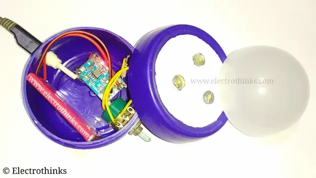
I simply soldered all components with some wires and assembled it in a plastic housing case (here I reused ♻ a Nivea Cream plastic box).
As you can see, the color of the box is blue, and it consumes the most brightness of the LEDs.
To fix it, I decided to color the top of the box with Whitner (you can use none removal white paint).
The white color reflects the light and lamp flashing most of the light energy.
To soften the brightness, I installed an old LED Bulb Cap on the top of the box and glue it with hard epoxy.
Step 4: Demo & Testing - Emergency LED lamp
Now, I am going to show you below the demo of this rechargeable, brightness adjustable emergency led lamp.
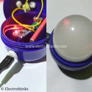
The lamp is successfully charged using a micro-USB mobile phone charger.
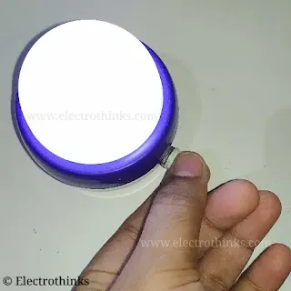
We can also increase or decrease the lamp's brightness using the potentiometer knop.


No comments
If you have any doubts or questions, please let me know. Don't add links as it goes to spam. Share your valuable feedback. Thanks