In this post, you are going to learn about switched-mode power supply (SMPS), circuit diagram, block diagram with working principle, and much more.
What is an SMPS?
A switched-mode power supply or in short SMPS is a power supply circuit that converts mains power using switching devices that are turned on and off at high frequencies, and storage components such as inductors or capacitors to supply power efficiently for the load.
Why Switched-mode power supply (SMPS) Used
Simple DC power supplies can be made with rectifiers followed by filter stages.
But they suffer from the changes in the input or, at load.
This initiated the development of a linear regulator (series/shunt) circuits.
They maintain a constant voltage by varying their resistance to counterbalance input voltage change or, load current demand change.
Still, the efficiency of these systems is poor, they are heavy and not flexible enough to be chosen for every application.
So switched-mode power supplies (SMPS) were designed.
They use a high-frequency switch (transistor) with varying duty cycles to maintain the output voltage.
The output voltage variations caused by the switching are filtered output by an LC filter.
SMPS systems own their origin back to the days when valve or, tube car radios needed large HT supply, e.g., 150V DC to be generated from an automobile power system of nominally 12V DC.
Today we find their application in the most sophisticated PC power supplies (e.g., 200 Watt ATX SMPS).
Switched-mode power supply Circuit Diagram
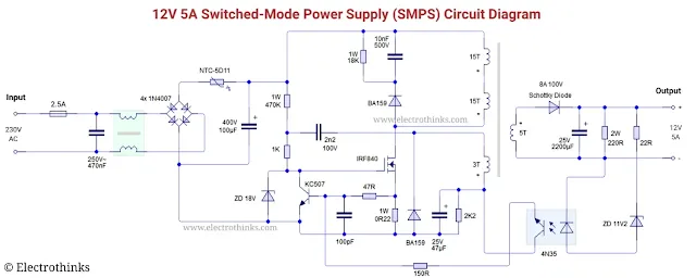
Schematic of 12V 5A switched-mode power supply (smps) circuit shown below.
Working principle of Switched-mode power supply circuit
Switched-mode power supplies (SMPS) are basically dc-dc converters.
If the input is AC, input is first rectified to get the DC.
So depending on the input, a SMPS may have two (dc-ac, ac-dc) or three (ac-dc, dc-ac, ac-dc) stages.
The block diagram is shows below the principle of an AC fed SMPS.
The input AC voltage is rectified, smoothed and supplied to a dc-ac converter.
This dc-ac convertion is done by puls width Modulation (PWM) technique.
Generally, transistors (MOSFET) are used as regulating switching device whose input is a train of pulses.
The duty cycle of the switching transistor is adjusted with a contol circuit.
The control circuit senses the output voltage and makes changes in order to keep output voltage constant irrespective of load and input voltages changes.
The output of the transistor is applied to the primary of a transformer.
The secondary voltage is rectified and soothed to give the required DC output.
This part corresponds to the second ac-dc conversion stage while the first ac-dc stage is connected at the input to the witching element.
Without the first ac-dc stage, this system can be operated from a battery or DC source.
The transformer provides necessary isolation.
Fuses are attached to both input and output for short circuit / overload protection.
The Filter at the input removes Radio Frequency Interference (RFI) and Electro Magnetic Interference (EMI).
Transistor, that serves as the main switching element, operates at a frequency above the audible range (25-250 KHz) to prevent noise.
Advantages of SMPS
- Low Weight and Smaller Size
- Higher Efficiency
- Wider AC input Voltage Range
- Reduced Cost
Disadvantages of SMPS
- Circuit Complexity
- Regulation
- Others
Applications
SMPS can be used in 3 configurations — (i) usual STEP-DOWN mode, (ii) STEP-UP mode or, (iii) INVERTED mode.
So, they are useful in large number of applications.
Some of them are listed below.
Linear regulators don't have such flexibility and don't have such versatile uses.
- STEP-DOWN mode: Generation of 5V supply for TTL based circuit from 12V battery.
- STEP-UP mode: Generation of 25V from a 5V supply in an EPROM programmer.
- INVERTED mode: Generation of double ended supply (±5V or ±12V) from a single ended supply for operational amplifier.


hi, good day, May I know what part of an SMPS or what device is responsible for feedback?
ReplyDeletecan you share saprate information of MOSFET circuit.
ReplyDeletein logistic which type of SMPS USED AND WHATS IS WORKING
ReplyDeleteI have been enlightened by the article on SMPS thanks for this.I wish to receive such articles from you.
ReplyDelete