
In this electronics project, I will show you step by step to make a simple DIY Induction heater where the optimum power supply voltage is 12V dc and the output power is 60 watt.
It is a push-pull oscillator circuit or the so-called ZVS driver and the scheme is so popular that there is lots of Chinese production.
Let's make it!
Components list
The following components are required to make this project.
- T1, T2: IRFZ44 mosfet (2 pcs)
- D1, D2: UF4007 diode (2 pcs)
- D3, D4: 1N4742 zener (2 pcs)
- R1, R2: 10KΩ resistor (2 pcs)
- R3, R4: 1W 470Ω resistor (2 pcs)
- C1: 2.2uF 630V capacitor (1 pcs)
- L1: 50-200µH Toroidal Inductor 5A (1 pcs)
- Tr1: 18G copper wire (as per required)
- Small size PCB/Veroboard (1 pcs)
Induction heater Circuit diagram
Schematic of induction heater with the average point of the coil circuit shown below.

Circuit working explanation
There are several variants of the induction heater scheme.
But, the above induction heater circuit is a bit more stable than two chokes without midpoint.
As I have said before, the scheme often used for constructing simple induction heaters.
In fact, it is a resonant converter, which was built as an auto-generator.
Here, each arm of the circuit must be treated as a separate oscillator.
The circuit worked from 3.5 V, and the power supply should be sufficient to trigger the FETs.
I used the N-channel IRFZ44, Choke (L1) is taken from a computer ATX power supply where the core is made from iron powder.
Gate resistors have two functions:
- Simultaneously limit the MOSFETs (T1, T2) gate current.
- Limit the current of Zener (D3, D4).
The Zener (D3, D4) prevents voltage increase through the gate and protects FET from breakdown, hence they maintain a stable operating voltage.
When the induction heater circuit powered from a stable source of 12V no need for Zener.
The transformer primary winding is connected in parallel with a capacitor (C1) to form a resonant circuit.
By changing the parameters of these components, the working frequency of the generator can be changed.
Although, it is not optimal due to the absence of the scheme for FETs regulation and good oscillator.
Large currents flow through the circuit, and the capacitor also operates in hard conditions.
Particularly, if the circuit is used as an induction heater, i.e. if the core is absent or it is not closed. Therefore, I advise you to use a battery of capacitors connected in parallel with a total capacity of 1 to 4.7 microfarads and a voltage of 630-1600V (optimally is 1000V). In the case of the capacitor bank, all should have the same capacity and voltage.
Assembling and Soldering the Components
Now, I simply assembled the components in a PCB and soldering according to the circuit diagram.

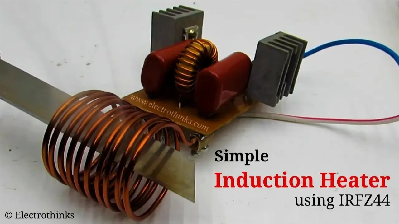
Demo & Testing - Induction heater
Finally, I connected the circuit board with an 18V nickel-cadmium battery and test it.

Showing a demo of this simple Induction heater where the metal plate is being heated.


No comments
If you have any doubts or questions, please let me know. Don't add links as it goes to spam. Share your valuable feedback. Thanks