In this electronics project, I will show you step by step to make a mini FM Transmitter using single transistor.
Yes! this is really mini where the circuit can run at 1.5 volt and can be used as a long-range spy.
Let's make it!
Step 1: Components list
The following components are needed to make this transmitter circuit.
- Q1: Any NPN Transistor - BC547, BC548, 2N2222, etc. (1 pcs)
- R1: 4.7Ω Resistor (1 pcs)
- R2: 100Ω Resistor (1 pcs)
- R3: 10KΩ Resistor (1 pcs)
- L1: 28G Copper Wire (1 pcs)
- C1: 30pF Capacitor (1 pcs)
- C2: 0.01nF Capacitor (1 pcs)
- C3, C4: 0.01µF Capacitor (1 pcs each)
- C5: 1µF Electrolytic Capacitor (1 pcs)
- M1: Electret Condenser Microphone (1 pcs)
- Small Veroboard (1 pcs)
- B1: 1.5V Battery (1 pcs)
Step 2: FM transmitter Circuit diagram
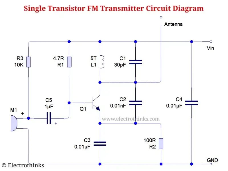
Schematic of single transistor FM transmitter circuit shown below.
Circuit explanation
The circuit is simple and easy to make.
An FM transmitter is a low-power FM radio transmitter that broadcasts a signal wirelessly with a specific frequency to a standard FM radio or mobile device.
The main component of this circuit is a single transistor and a coil.
Here, you can use any NPN transistor (Q1) as your wish (I used here BC547).
This transmitter cool part is a coil, take 28 gauge copper wire and warped five-time and the coil has been created.
Note: If you the making this coil the wrong way you can never create this FM Transmitter. The correct rule is to be this coil will have the same straight line with both legs where the coil weight is 5mm, and height is 4mm.
A capacitor (C1) is used to keep the coil frequency.
The resistor (R1) connected from VIN positive to transistor base pin that reason to active the transistor (Q1).
To filter transistor base volt, the capacitor (C2) connected with the base pin and ground.
The capacitor (C3) between the collector and emitter influences the voltage on the emitter to turn the transistor on and off. It does this by constantly monitoring the voltage on the tuned circuit and passing the change to the emitter.
The negative voltage to the transistor emitter pin can be done through the resistor (R2) for a little bit volt.
The capacitor (C4) used to filter the battery (B1) voltage.
The input voltage is 1.5V and perfect for this circuit, entering more than 1V will destroy the transistor (Q1).
The reason a negative volt is entered into the emitter pin and the VIN positive volt entering the collector pin.
To transmit an audio sound or music through this FM transmitter a condenser microphone (M1) connected base pin through capacitor (C5) and ground.
A safety resistor (R3) is connected to the condenser positive teminal to the VIN.
Step 3: Assembling and Soldering Components
Now, I put the components one by one on a small Veroboard and soldering it according to the schematic.
After soldering all components, I connect a 1.5V battery to the FM transmitter circuit board as an input supply.
Also, I simply connect an RC Antenna for large distance transmission.
Step 4: Demo & Testing - FM Transmitter
After powering the circuit board I start to scan the FM transmitter signal in my phone radio application.
Finally, I got the signal is 92.9 MHz!
But, when it transmits any audio sound or music through the FM transmitter, this process may change MHz.
The reason there is no crystal in it and you can see below that the MHz signal has changed to 9.06 MHz.
After tuning and selecting the 90.6 Mhz, I start to hear the broadcast sound from this homemade FM transmitter in my radio app.
Now, the question is how far will it work? — I keep walking around with the phone, and I saw the small single transistor FM transmitter working at 500 meters with the antenna.


can i use 27pf instead of 30 pf ?
ReplyDeleteYes! You can use between 18-47pF capacitor.
DeleteHowever, the transmitter signal can fluctuate slightly and be transmitted with a different MHz signal.
isn't funny, '500m range'?
ReplyDeletewhat do you mean? do you think it can reach 500m?
DeleteUna pregunta el capacitor C4-0.01uf que numero tiene.
ReplyDeleteThe 3 digit ceramic capacitor code 103 stands for 10 nF (or 0.01uF).
DeleteWill 4202bd transistor work
ReplyDeleteBuenas tardes tengo una pregunta el capacitor C2 0.01nF que numero tiene.
ReplyDeleteHow can we add AUX Cable instead of MIC in this circuit? Plz. reply
ReplyDeleteReplace ground of mic with the longest prong in the AUX cable and replace signal with one of the smaller prongs.
Delete