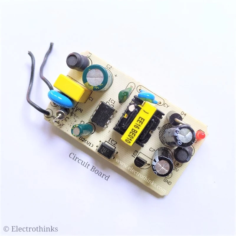
12 Volt 2 Amp switch mode power supply takes an AC input of 100-240V and gives stabilized 12V 2A DC output with low ripple and low interference.
The circuit uses an integrated circuit LP2704A of a series of circuits LP2703A/LP2703A./LP2704A package (SOP8).
Optimized circuit design with high rationality combined with high performance and price ratio SOI production process for cost-effective AC to DC converters.
With the usual PWM (pulse wide modulation) controller is different, it uses a simple on/off control method to stabilize the output voltage.
Integrate a 700 V power MOSFET, the working frequency is 140 kHz, high voltage switches current source, current limiting, and thermal shutdown circuit.
The thermal shutdown circuit detects the temperature of the junction, the threshold is set at 130 °C (typical) and has a hysteresis range of 55 °C (typical).
In the Undervoltage state, the prohibition time of power MOSFET switching exceeds the usual 1.2 seconds until the end of the Undervoltage state.
This power controller can work in a typical small flyback supply and it doesn't even need an auxiliary winding.
Circuit Diagram
Schematic of 12V 2A Switch-mode power supply circuit with IC LA2704A shown below.
Transformer Details
The transformer is a small ferrite EE16 BE010 model whose central column has an air gap of 0.4 mm. Primary (P) has 165 turns of wire diameter 0.15 mm. Secondary (S) has 2x 20 turns of wire 0.4 mm.
Switching supply is not for beginners, because most of its circuits are connected to fatal mains voltage. When bad design, the mains voltage can reach the output! Capacitors can remain charged to dangerous voltage even after disconnected from mains. Everything you do at your own risk, for any injury to health or property I do not take responsibility.


Hi where can I find this IC TLP2704. Can you share link for IC?
ReplyDeleteTLP2704 is a High Speed Optocoupler, 30V 5000Vrms. You can also use TLP281-4 or TLP291-4.
DeleteWhat should be the primary inductance of the transformer?
ReplyDeleteIt should be 1900µH.
DeleteHi, can you send to the figure of windings because you make secondary windings as a sandwich (2*20) .
ReplyDeleteIn my mind ,
1- half of secondary 20 turns 0.4 mm
2- primary 165 turns 0.15 mm
3- half of secondary 20 turns 0.4 mm
This is right??
In the schematic, the primary winding (P) consists of 165 turns with single piece of 0.4mm copper wire, and the secondary winding (S) consists of 20 turns with two pieces of 0.4mm copper wire. You can wind the secondary with a single 0.8mm copper wire as well, but the number of turns remains 20.
DeleteThanks for your fast response.
DeleteCan I use TNY268 instead of LP2704. Because it is not available in my country.
If I will use TNY268, what is the modification in this circuit?
Thanks
No, you cannot use TNY268 as a direct replacement for LP2704.
DeleteThey are different members of the TinySwitch series and have different specifications and features.
TNY268 is designed for lower power applications up to 15W, while LP2704 is suitable for higher power applications up to 36W.
They have different integrated features and performance characteristics, so it's important to choose the appropriate IC based on your specific application requirements.
Always refer to the manufacturer's datasheets and technical documentation for proper selection and compatibility.
This comment has been removed by the author.
ReplyDeleteI could not understand the diode D2 R31M value and please tell me it is and also tell me the wattage of the two resisters R3, R4
ReplyDeleteSure, here's the corrected information: D2 is a RS1M Fast Recovery Diode with a voltage rating of 1000V and a current rating of 1A. All resistors in the circuit have a power rating of 1/4W.
Deletehi mr subhajit ic shown on pcb is DIP8 and the datasheet shows SOP8. what is the number of ic can you share the detail . as per datasheet LP2704A SOP8 pack candeliver upto 6watt.
ReplyDeleteregards
sir i tried to find LP2704A it is sop8 package and what your photo show is dip 8.
ReplyDeletelp2704a is a 6 watt ic smd type i tried to locate dip ic on the entire website but no success pl
help me to find the same ic.
Yes, I know that! It is a Chinese-manufactured device, and the LP2704A DIP-8 is specifically designed for this circuit board. We can't find or buy this IC online, but you can try looking for the LP2704A SOP-8, which is an SMD IC and can be found on AliExpress.
Delete