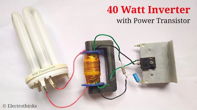
In this electronics project, I will show you a simple and cheap 40 watt inverter with a power transistor. This inverter circuit required minimal components. It can invert the 12V DC to high voltage AC which allows you to power up to 40W fluorescent tubes (or two 20 watt tubes in series).
The circuit is very simple, inexpensive and easy to build. Let's make it!
Please use safety equipment since this circuit work with high voltage electricity. Do not touch the outputs, there is a chance for a fatal shock.
Components List
The following components are required:
- Q1: Power transistor (1 pcs) - TIP35 or TIP3055 or 2N3055 or equivalent.
- T1: U-shape High-frequency Transformer core (2 pcs)
- Plastic Bobbin (1 pcs)
- 0.44mm Enamelled Copper wire
- 0.2mm Enamelled Copper wire
- Insulating tape
- R1: 180Ω, 1W Resistor (1 pcs)
- C1: 100uF, 16V Capacitor (1 pcs)
- Aluminium Heat-sink (1 pcs)
- Flexible Wires (as per required)
- Fluorescent lamp (1 pcs)
Circuit Diagram
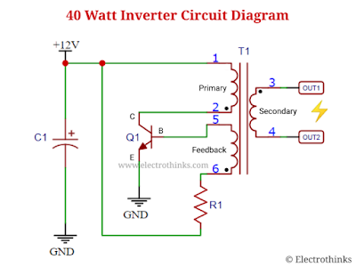
Schematic of 40 watt inverter circuit shown below.
Circuit Explanation
The working principle of this 40W inverter circuit is simple. Inside the circuit, a single NPN power transistor (Q1), a step-up transformer (T1), and a capacitor (C1), resistor (R1) is used.
When the inverter circuit board gets the 12V DC input, the capacitor (C1) charged and the base of the transistor (Q1) starts opening as it's biased by the resistor (R1). The current through transformer primary winding (L1) starts rising rapidly and reaches the threshold level within no time.
But at the same time, an opposite (but low) voltage starts rising across the auxiliary feedback winding (L3) of the transformer. Thus ultimately blocks current flow through primary winding (L1). As there's no more current flow in the auxiliary feedback winding (L3).
This process repeats itself again and again very fast, depending on various parameters. Hence, an AC high voltage generates (over 1,000 volts) in transformer secondary winding (L2) with the high frequency and that's powered the loads up to 40 watt.
Transformer Winding Details
You will need two U-shape High frequency transformer core. All windings (L1, L2, and L3) are wound on the same core. Take a plastic Bobbin over the core to wind L1, L2, L3 on. Leave 50mm of wire at each end or soldaring with fexible wires of the coils.
Primary Winding (L1): Wind 60 turns of 0.44mm diameter enamelled copper wire on the first layer and put a layer of insulating tape over it.
Secondary Winding (L2): This coil has 500 turns of 0.2mm enamelled copper wire in five layers. Wind one layer and then insulating tape over it. Do the same for the next four.
Feedback Winding (L3): Wind 13 turns of 0.44mm enamelled copper wire on the core and then insulating tape over that.
Demo and Testing
In this demo video, you will see the test of the inverter circuit with TIP35. Where, I simply powered the circuit by a 7.4V DC source from two series lithium batteries and the circuit converted the DC voltage to high voltage AC and the lamp light up.
This inverter circuit is should be used for 220V fluorescent lamps. It will work with 120V units just fine but will shorten the life of the fluorescent tube. In the case, the tube doesn't light up immediately, then reverse the connections of L1 winding. If the tube still doesn’t light up, check all wiring connections correctly.


No comments
If you have any doubts or questions, please let me know. Don't add links as it goes to spam. Share your valuable feedback. Thanks