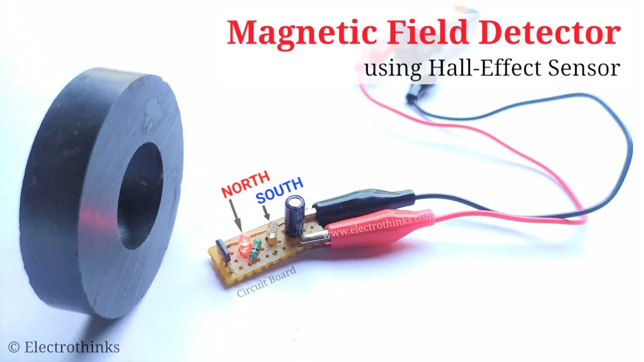
In this electronics project, I will show you a Magnetic field detector using Hall-effect sensor, where the detector indicates the presence and polarity of the magnetic field, whether it is a neodymium magnet, ring magnet, or disc magnet. The operating voltage for this detector range from DC 3.7 V to 12 V and current 300 mA to 800 mA.
Let's make it!
Components List
The following components are required for this project:
- U1: Hall Effect Sensor (1 pcs) - 276, 277, etc.
- LED1: 3mm Red LED (1 pcs)
- LED2: 3mm Blue LED (1 pcs)
- R1: 1KΩ resistor (1 pcs)
- C1: 1uF 25V capacitor (1 pcs)
- Veroboard or Breadboard (1 pcs)
- Connecting wires
- B1: 9V Battery (1 pcs)
Circuit Diagram
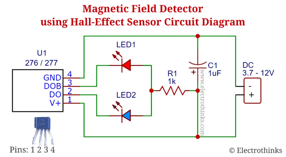
Schematic of magnetic field detector using 276/277 hall sensor circuit shown below.
Circuit Explanation
The magnetic field detector circuit is simple. The main component of this circuit is the 4-pin Hall-effect sensor that detects or measures the magnetic field and works on the principle of the Hall effect.
There are two basic types of Hall effect sensors:
- Linear Hall sensor: The output voltage is proportional to the magnetic induction.
- Logical Hall sensor: The output can be present only in two states. It changes its state on a certain threshold and may have a hysteresis.
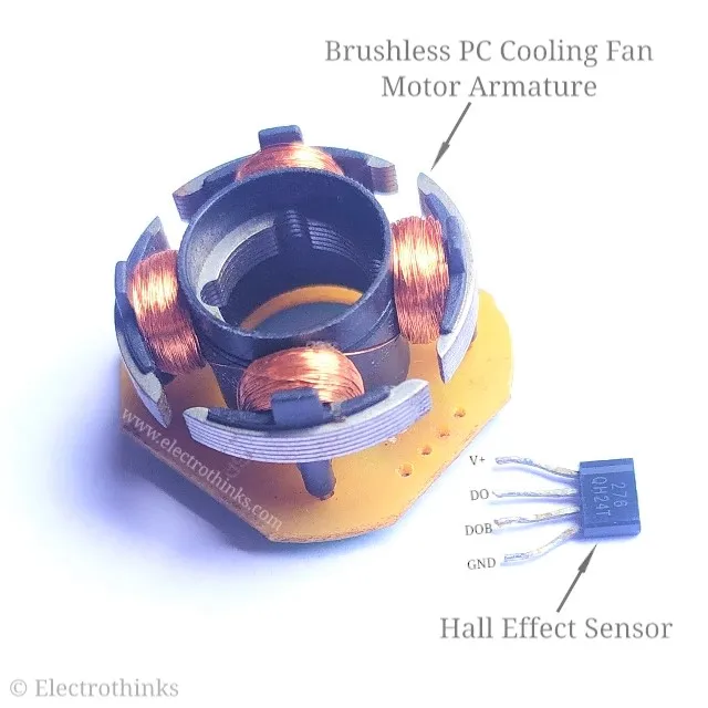
Here, I used a hall sensor marked 276 (you can use 277) from a brushless PC cooling fan. Among them, logical sensors are used.
When the circuit is powered, the Hall effect sensor (U1) is initially activated, and the sensor pin-3 (DOB) gives an output voltage, and LED1 will become a high state. Due to the slight asymmetry of the sensor, the same output is always open in low or magnetic north pole or no magnetic field condition.
But if the magnetic south pole brings near the sensor, the sensor pin-3 turns OFF, pin-2 (DO) gives an output voltage, and LED2 will become a high state. A resistor (R1) is used to limit the current for the LEDs, and a capacitor (C1) is used to maintain the input power.
Demo and Testing
In this demo video, you will see the test of the magnetic field detector using the 276 hall sensor. I power the circuit with a 9-volt battery, and it activates immediately.
The Red LED turns ON, which indicates there is a magnetic north pole or no magnetic field. Similarly, when the Blue LED turns ON, it indicates there is a magnetic south pole.
In this way, you can easily identify the polarity of a magnet or magnetic field.


No comments
If you have any doubts or questions, please let me know. Don't add links as it goes to spam. Share your valuable feedback. Thanks