This article will provide detailed information about Half-Wave Rectifier, including circuit diagrams, working principles, rectifier disadvantages, and more. Let's get started!
Half-Wave Rectifier Circuit
It is a circuit in which only a single diode rectifier is used to conduct ac supply current in the same direction through a load during the positive half-cycle. Therefore, the output is always dc according to the load after every half-wave of the input AC supply.
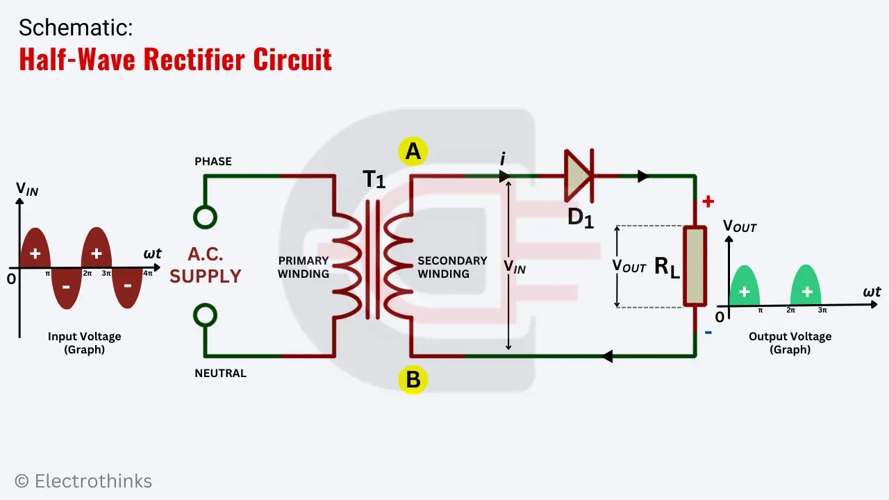
Half-Wave Rectifier Circuit Diagram
The schematic of a half-wave rectifier circuit is shown below.
Working Principle of Half-Wave Rectifier Circuit
>The following animations show you the exact working of the circuit.
When the circuit is powered from the Mains supply, the primary winding of the transformer (T1) transfers a step-up or step-down AC voltage to the secondary winding AB ends and changes polarity after each half-wave.
Case 1. During the positive half-cycles, end A becomes positive and end B negative. Under this condition, the diode (D1) becomes forward-biased and current flows through the load (RL) to end B.
Case 2. During the negative half-cycles, end A becomes negative, and end B positive. This makes the diode (D1) reverse-biased and causes zero current flow.
Thus the current through the load always flows in the same direction, and a pulsating dc output is obtained across the load, which is further smoothed with the help of filter circuits.
Disadvantages of Half-Wave Rectifier Circuit
The circuit has some disadvantages. They are,
- Load contain the alternating component. The pulsating dc output frequency is equal to the supply input frequency. This means that when the input supply AC completes one cycle, the output half-wave rectified waveform also completes the cycle. Therefore, the output carries frequency where extensive filtering is required to prevent it, which is expensive.
- Output is Low. This rectifier circuit provides a power output at half the time of the AC supply input. So, a maximum of 40.60% of AC power is converted into DC power.


No comments
If you have any doubts or questions, please let me know. Don't add links as it goes to spam. Share your valuable feedback. Thanks