
Many electronic projects or devices require a dual-voltage power supply to operate correctly. This DC power supply output can be either a dual positive (+Ve) or a combination of both positive (+Ve) and negative (-Ve). In this project, I will show you such dual DC power supply circuit designs using two different fixed voltage regulators. Let's get started!
As we know, fixed voltage regulators are of two types, positive voltage regulators provide a positive output voltage, whereas negative voltage regulators give a negative output voltage. Therefore, the project is divided into two parts -
- Dual DC Power Supply for Positive Voltage
- Dual DC Power Supply for Positive & Negative Voltage
But, these power supplies can provide a maximum output of 1A current. To increase the output current, you need to make some modifications.
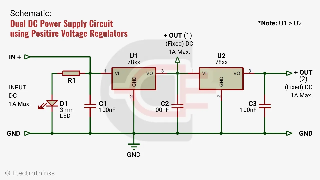
Dual DC Power Supply for Positive Voltage
This power supply design is based on two positive voltage regulators that can provide dual positive output voltages simultaneously. The project inculding circuit diagram, required components list, and working explanation.
Circuit Diagram
Schematic of the dual dc power supply circuit using positive voltage regulators is shown below.
Components List
The following hardware components are required,
DC Power Supply. An unregulated step-down power supply, including a full-wave bridge rectifier and a filtering capacitor, is used to step down the mains AC voltage to DC voltage (+Ve, GND) to power the circuit.
Positive Voltage Regulator IC. Two linear voltage regulator ICs (U1 & U2) from the 78xx series voltage regulators, are utilized here to regulate the unregulated DC voltage. The output of IC (U1) must be higher than that of IC (U2) input. You can find the minimum required input voltage to operate the positive voltage regulator ICs in the 78xx series datasheet.
Capacitor. Two non-polar 100nF capacitors are used in parallel with this dual power supply circuit. They are used on both the input and output sides for the purposes of smoothing, filtering noise, and improving the transient response of the DC voltage.
LED. A 3mm LED (D1) used to indicate the input power.
Resistor. The current limiting resistor is used with the LED (D1). You should calculate the LED serise resistor before impliment in the circuit.
Working Priciple
The working principle of this dual dc power supply circuit is simple. When the circuit receives the minimum operating input DC voltage from an unregulated DC power supply, the positive voltage regulator IC (U1) regulates the +Ve input and provides a first output. Then this output DC voltage farther step-down by a lower rating positive voltage regulator IC (U2) and that provides a second output. This way the circuit provides +Ve dual DC outputs continously.
The following Input and output table for a dual DC power supply circuit when two different positive voltage regulator ICs are combined.
| IC (U1, U2) | Max. DC Input | Fixed DC Output | Schematic |
|---|---|---|---|
| 7808, 7805 | DC 12V to 15V, 1A | DC +8V, +5V, 1A | View |
| 7809, 7805 | DC 12V to 15V, 1A | DC +9V, +5V, 1A | View |
| 7809, 7806 | DC 12V to 15V, 1A | DC +9V, +6V, 1A | View |
| 7810, 7805 | DC 15V to 20V, 1A | DC +10V, +5V, 1A | View |
| 7810, 7806 | DC 15V to 20V, 1A | DC +10V, +6V, 1A | View |
| 7812, 7805 | DC 15V to 20V, 1A | DC +12V, +5V, 1A | View |
| 7812, 7806 | DC 15V to 20V, 1A | DC +12V, +6V, 1A | View |
| 7812, 7808 | DC 15V to 20V, 1A | DC +12V, +8V, 1A | View |
| 7812, 7809 | DC 15V to 20V, 1A | DC +12V, +9V, 1A | View |
| 7815, 7808 | DC 18V to 24V, 1A | DC +15V, +8V, 1A | View |
| 7815, 7809 | DC 18V to 24V, 1A | DC +15V, +9V, 1A | View |
| 7815, 7810 | DC 18V to 24V, 1A | DC +15V, +10V, 1A | View |
| 7815, 7812 | DC 18V to 24V, 1A | DC +15V, +12V, 1A | View |
| 7818, 7810 | DC 24V to 30V, 1A | DC +18V, +10V, 1A | View |
| 7818, 7812 | DC 24V to 30V, 1A | DC +18V, +12V, 1A | View |
| 7824, 7815 | DC 30V to 35V, 1A | DC +24V, +15V, 1A | View |
| 7824, 7818 | DC 30V to 35V, 1A | DC +24V, +18V, 1A | View |
Dual DC Power Supply for Positive & Negative Voltage
This power supply design is based on positive & negative voltage regulators, which can simultaneously provide both positive and negative output voltages. The project inculding circuit diagram, required components list, and working explanation.
Circuit Diagram
Schematic of the dual dc power supply circuit using positive and negative voltage regulator is shown below.

Components List
The following hardware components are required,
DC Power Supply. An unregulated dual DC power supply, including a full-wave bridge rectifier and two filtering capacitor, is used to step down the mains AC voltage to DC voltage (+Ve, -Ve, GND).
Positive Voltage Regulator IC. A single linear voltage regulator IC (U1) from the 78xx series positive voltage regulators is utilized here to regulate the unregulated DC voltage to a positive voltage. Usually, this IC is used in series with the +Ve input terminal.
Negative Voltage Regulator IC. A single linear voltage regulator IC (U2) from the 79xx series negative voltage regulators is utilized here to regulate the unregulated DC voltage to a negative voltage. Usually, this IC is used in series with the -Ve input terminal. You can find the minimum required input voltage to operate the negative voltage regulator ICs in the 79xx series datasheet.
Capacitor. Four non-polar 100nF capacitors are used in parallel with this dual power supply circuit. They are also used on both the input and output sides for the purposes of smoothing, filtering noise, and improving the transient response of the DC voltage.
LED. A 3mm LED (D1) used to indicate the input power.
Resistor. The current limiting resistor is used with the LED (D1).
Working Priciple
The working principle of this dual DC power supply circuit is slightly different from that of a positive dual DC power supply. When the circuit receives the minimum operating input DC voltage from an unregulated dual DC power supply, the positive voltage regulator IC (U1) regulates the +Ve input and provides a first output. On the other hand, the negative voltage regulator IC (U2) regulates the -Ve input and provides a second output. The ground (GND) serves as a common reference for both outputs. This way the circuit provides +Ve & -Ve dual DC outputs continously.
The following Input and output table for a dual DC power supply circuit when positive & negative voltage regulator ICs are combined.


No comments
If you have any doubts or questions, please let me know. Don't add links as it goes to spam. Share your valuable feedback. Thanks