

The NTC Temperature Sensor module is based on a small NTC thermistor, which is used for measuring ambient temperature. It provides analog output signals that can be easily interfaced and read by microcontrollers such as Arduino, Raspberry Pi, ESP32, etc. The data is transmitted using a single-wire analog protocol.
NTC Temperature Sensor Module Specifications
The quick specifications of this sensor module is given below:
- Type: Analog
- Module: Temperature Sensor
- Operating Voltage: DC 5V
- Temprature Measurement Range: -55°C to 125°C [-57°F to 257°F]
- Measurement Accuracy Range: ±0.5C (between the range -10°C to 85°C)
- Board Dimantions (L x W x H): 24.5mm x 16mm x 7mm
- Weight: 1gm
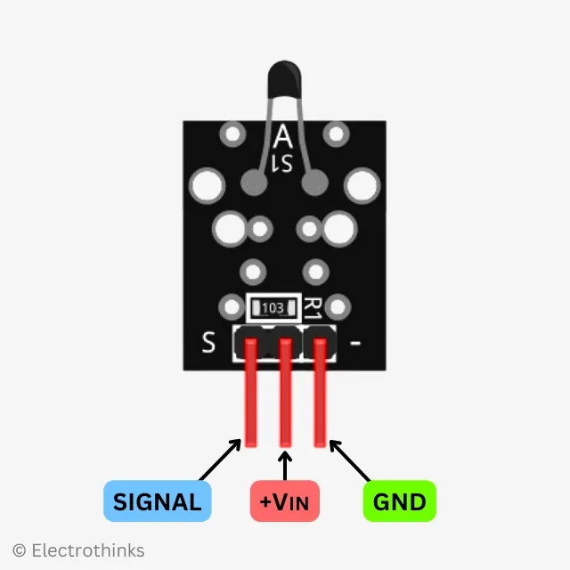
NTC Temperature Sensor Module Pinout
|
The module has 3 male header pins those are -
|
NTC Temperature Sensor Module Circuit Diagram
Schematic of the ntc temperature sensor module circuit is shown below.
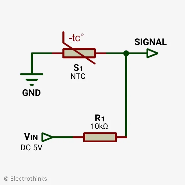
Components are used in the circuit - S1: 10kΩ NTC, and R1: 10kΩ Resistor.
The NTC (S1) is connected in a voltage divider configuration with a fixed resistor (R1). The output signal (S) voltage is taken from the junction between the NTC and the fixed resistor.
The working principle of the circuit is simple. The NTC (S1) in the module acts as a non-linear resistor that changes its resistance based on the ambient temperature. When the temperature increases by every 1 degree Celsius, the resistance of the NTC will decrease by 5%. This output signal voltage is directly proportional to the ambient temperature, and a programmed microcontroller can easily measure it.
How to Interface NTC Temperature Sensor module with Arduino
Connection diagram of the NTC Temperature Sensor module with an Arduino is shown below.
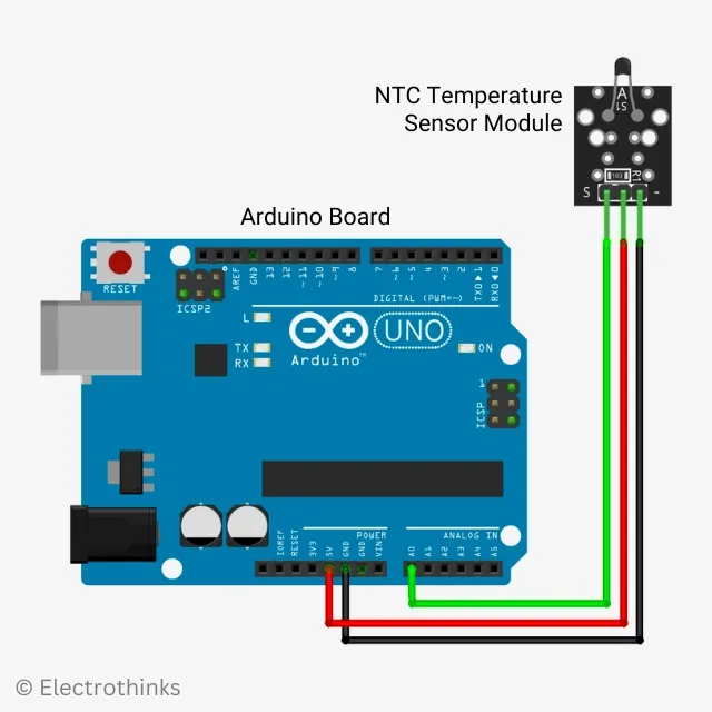
You will need to connect the power pin (middle) and ground pin (-) of the photoresistor module to +5V and GND on the Arduino, respectively. The module signal pin (S) connect to analog pin A0 on the Arduino.
| Photoresistor Module | Arduino |
|---|---|
| S | Pin A0 |
| middle | +5V |
| – | GND |
The Arduino's analog input pin is used to read the voltage at the output of the voltage divider. The analog input pin can measure voltages between 0 and 5V and converts them into a digital value.
Here's a basic Arduino sketch for the NTC module. It utilizes the Steinhart-Hart equation to measure ambient temperature and then prints the corresponding temperature in Celsius.
const int thermistorPin = A0;  // Connect signal pin (S) of NTC Temperature Sensor module to Arduino analog pin A0

// Thermistor parameters for Steinhart-Hart equation
const float A = 0.001125308852122;     // Steinhart-Hart coefficient A
const float B = 0.000234711863267;     // Steinhart-Hart coefficient B
const float C = 0.000000085663516;     // Steinhart-Hart coefficient C

void setup() {
  Serial.begin(9600);  // Initialize serial communication
}

void loop() {
  int rawValue = analogRead(thermistorPin);  // Read the raw sensor value
  float voltage = rawValue * (5.0 / 1023.0);  // Convert sensor value to voltage (assuming 5V reference)
  float resistance = (5.0 - voltage) / voltage;  // Calculate resistance of thermistor
  float steinhart;  // Temperature variable

  // Apply Steinhart-Hart equation to calculate temperature
  steinhart = 1.0 / (A + (B * log(resistance)) + (C * pow(log(resistance), 3)));
  steinhart -= 273.15;  // Convert temperature to degrees Celsius

  Serial.print("Temperature: ");
  Serial.print(steinhart);
  Serial.println(" °C");

  delay(1000);  // Wait for a second before taking the next reading
}
Once you upload the code to your Arduino board, open the Serial Monitor in the Arduino IDE at a baud rate of 9600. You should see the measured ambient temperature printed every second in the Serial Monitor.


0 Comments