
In this project, I will show you how to make a full sinusoidal inverter using EGS002 SPWM driver board, which can convert the 12V DC to 220V AC with 50/60Hz pure sine wave. You can use this inverter to power household appliances up to 1000 watts during emergency situations when electricity is not available. It can also be highly useful for camping and outdoor work where electricity is unavailable, and you need to operate tools like drills, grinders, soldering equipment, and more.
Let's make it!
Components List for 1kW Pure Sine Wave Inverter
The following components are required to make this powerful inverter:
| Name | Value | Qty. |
|---|---|---|
| P1: Inverter Driver Module | EGS002 SPWM | 1 |
| Q1 to Q12: N-Channel MOSFET | IRF3205 | 12 |
| Q13: NPN Transistor | TIP31 | 1 |
| D1 to D4: Diode | 1N4148 | 4 |
| BR1: Bridge Rectifire | 1N4007 | 4 |
| R1 to R4: Resistor | 10Ω, 1/4W | 4 |
| R5 to R8: Resistor | 10kΩ, 1/4W | 4 |
| R9: Shunt Resistor | 0.01Ω | 1 |
| R10, R11: Resistor | 100kΩ, 1/4W | 2 |
| R12: Resistor | 2.2kΩ, 1/4W | 1 |
| S1: NTC Temprature Sensor | 10kΩ | 1 |
| POT1: Resistor | 10kΩ | 1 |
| C1: Capacitor | 100uF, 25V | 1 |
| C2: Capacitor | 10uF, 25V | 1 |
| C3: Capacitor | 470nF | 1 |
| C4: Capacitor | 2.2uF, 350V | 1 |
| C5: Capacitor | 2.2uF, 25V | 1 |
| T1: UPS Transformer | 7V /220V, 500-1000W | 1 |
| U1: Voltage Regulator | IC 7805 | 1 |
| F1: DC Fan | 12V, 25mA | 1 |
| Heat Sink | Aliminium | 1 |
| Insulation Pads with Plastic Washers | Rubber/Plastic | 6 |
| Washers | Plastic | 6 |
| 17 Header Pin | Female | 1 |
1kW Pure Sine Wave Inverter Circuit Diagram
Schematic of the 1kw pure sine wave inverter circuit using egs002 spwm driver board is shown below.
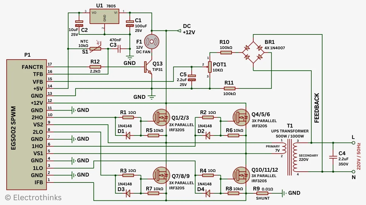
The working principle of the EGS002 SPWM based inverter circuit is simple. The inverter circuit includes voltage, current, and temperature protection mechanisms, LED warning indicators, and fan control.
The main component of this inverter circuit is the EGS002 driver board, specifically designed for a single-phase sinusoidal inverter. It utilizes the ASIC EG8010 as the control chip and the IR2110S as the MOSFET driver chip.
This intregrated circuit board serves as a DC-DC-AC two-stage power converter system or a DC-AC single-stage low-power frequency transformer system. Its purpose is to boost the input voltage and generate a 50Hz (default) pure sine wave output with high accuracy and minimal harmonic distortion. This is achieved with the assistance of an external 12MHz crystal oscillator. The output voltage of the inverter circuit can be adjusted to 220V AC using the trimmer (POT1).
The driver board continuously measures the output load current through IFB pin for overcurrent protection detection. If, for any reason, the current exceeds the inverter's rated current, the module will shut down all power MOSFETs to reduce the voltage to zero. This function primarily serves to protect both the power MOSFETs and the connected load.
The NTC temperature sensor operates as a simple voltage divider circuit. Voltage varies in response to changes in NTC resistance, allowing us to obtain the corresponding temperature.
On the driver board, the overtemperature voltage threshold for the TFB pin is set at 4.3V. If the set voltage exceeds, it will trigger a shutdown of all power MOSFETs, reducing the voltage to zero. Once the overtemperature protection is activated, the driver module will re-evaluate the environmental temperature. If the voltage at pin TFB falls below 4.0V, the overtemperature protection will be turned off, and the inverter will operate normally. [If overtemperature protection is not required, this pin should be grounded.]
1kW Pure Sine Wave Inverter PCB Design
As you can see from the inverter schematic, it's evident that this is a complex circuit. Constructing it on a veroboard would be time-consuming, risk of shorts and unprofessional.
Therefore, I'm sharing a custom-designed 1kW pure sine wave inverter PCB Gerber file. You can download it and order it at very affordable price from PCBWay.

|
| This is the Parts Placement Diagram for the Inverter PCB. |
Important: Use Heatsink Insulation Pads with Plastic Washers for the Transistors (Q4,Q5,Q6), and (Q10, Q11, Q12).
I ordered the custom-designed PCB and the Musical Tesla Coil from www.PCBWay.com, and after a few days of waiting, I received the high-quality PCBs and the device.


9 Comments
Hello! Thank you for sharing. The link for Gerbers is not working, can you please fix this? Or if possible, share another link for me. Thank you!
ReplyDeleteFixed: Click on Gerber file link.
DeleteHi,
ReplyDeleteAppriciating your effort to designing the PCB and sharing it for other makers, I would like to ask a question that is the MOSFET Gate driver circuit is enough? sharing the same gate resistor for more than one MOSFET is not a good practice I guess.
Thanks in advace for addressing my query.
Hello, thanks for your sharing can you tell me what type of transformer is used in the output, I can't find the example mentioned
ReplyDelete300W/500W/1000W UPS Transformer
DeleteI can't find battery connection , change over ckt , charging ckt , over load protection nothing is there
ReplyDeleteThis inverter sounds really useful! It can power your home appliances during outages. Plus, it's great for camping. I like that it has safety features and LED indicators. It seems well-designed. https://inverterreview.com/tag/pure-sine-wave-inverters/
ReplyDeleteso the inverter board will run directly when 12v battery supplies. and also i will use for making computer ups so can i use 12v 20amp battery for 10-15min backup?
ReplyDeleteCan you put the crt sinusoidal output
ReplyDelete