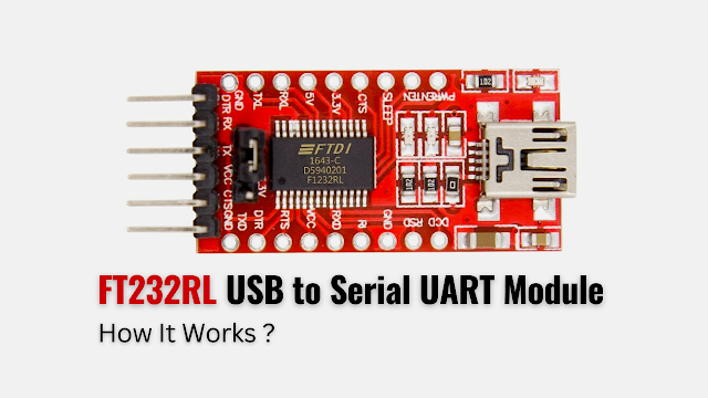
The FT232RL module is a mini USB to serial UART TTL 5V 3.3V converter circuit board designed for communication between a computer's USB port and the microcontroller's programming port. The module has a jumper on the circuit board that allows the board to be configured for either 3.3V or 5V, both for power output and IO level. This serial UART converter can be used to upgrade any legacy peripherals to USB. You can buy this module here!
Specifications of FT232RL USB to Serial UART Module
The quick technical specifications of this converter module is given below:
- Connector Type: Mini USB-B Port
- Module IC: FTDI FT232RL chip
- Operating Voltage: DC 5V/3.3V
- Max Current Draw: 500mA @5V; 50mA @3.3V
- Communication Indicators: RXD and TXD
- Data Transfer Rates: 183 Baud to 3 Mbaud (RS232, RS422, RS485) at TTL levels
- Receive Buffer: 128 Byte
- Transmit Buffer: 256 Byte
- Board Dimantions (L x W): 36mm x 18mm
- Weight: 4gm
Pin Configuration of FT232RL USB to Serial UART Module

The device pinout displays all the pins, with six being the main pins - DTR, RX, TX, VCC, CTS, and GND. The following groups depict all the pin types along with the function of each pin.
Power & Ground Pins Group
| Pins | Description |
|---|---|
| VCC | Operating DC supply voltage between +3.3V to +5.25V |
| 3.3V | Supply for external circuitry requiring a +3.3V nominal supply with a maximum current of 50mA |
| 5V | Supply for external circuitry requiring a +5V |
| GND | Device ground |
UART TTL & Control Pins Group
| Pins | Description |
|---|---|
| TX/TXD | Transmission of serial data |
| RX/RXD | Reception of serial data |
| DTR | Data Terminal Ready control output for reset or control the target microcontroller or device when establishing a connection |
| RTS | Request to Send control output for hardware handshaking |
| RI | Ring Indicator control input that wake up the USB host controller from suspend mode |
| DSR | Data Set Ready control input that manage the flow of data between connected devices |
| DCD | Data Carrier Detect control input that indicates the presence of a carrier signal on the communication channel |
| CTS | Clear to Send control input for hardware handshaking |
CBUS Pins Group
| Pins | Description |
|---|---|
| SLEEP | Indicates that the device going into USB suspend mode |
| TXDEN | Enable transmit data for RS485 designs |
| PWREN | Power control for high power, bus powered designs. This should be pulled high through a 10 kΩ resistor from VCC |
| TXL | Pulsing an LED upon transmission of data |
| RXL | Pulsing an LED upon receiving data |
FT232RL USB to Serial UART Module Circuit Diagram
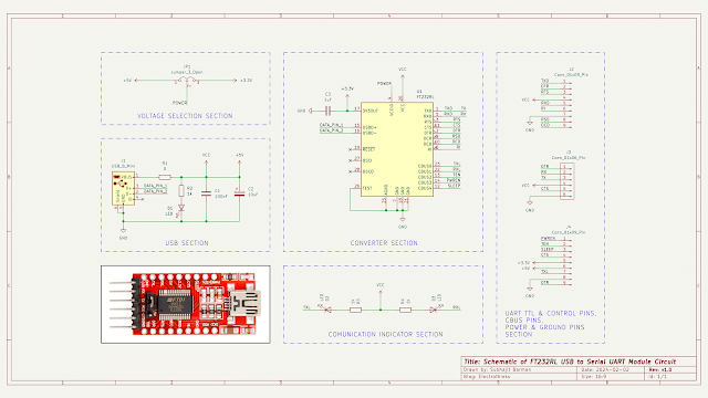
Schematic of FTDI FT232RL chip based USB to serial UART converter circuit is shown below.

The hardware components are used in the circuit are - FTDI FT232RL 28-LD SSOP IC (U1), Mini USB type-B (J1), 0-ohm resistor (R1), 1k resistor (R2, R3, R4), LED (D1, D2, D3), 100nF ceramic capacitor (C1), 10uF 10V tantalum capacitor (C2), 1uF ceramic capacitor (C3), 3 meal header pins (JP1), and 6 meal header pins (J3).
Working Principle of FT232RL USB to Serial UART Module Circuit
The FTDI module circuit is based on the FT232RL chip, serving as the core between the mini USB-B and serial ports interface. The package is fully integrated with 1024-bit EEPROM storing device descriptors and CBUS I/O configuration, USB termination resistors, and an integrated clock circuit that requires no external crystal. The circuit consists of five sections, each with different functionality.

- USB Section. A standard female mini USB Type-B port is integrated into the circuit board to receives power (VCC +3.3V to +5.25V) and communication data (D+, D-). This requires a male mini USB Type-B to male USB Type-A cable to connect the module to the to the computer.
- Converter Section. This section translates USB data signals from the computer into UART TTL signals (0V for logic low and 3.3V or 5V for logic high) that the microcontroller or embedded system (RS232/RS485/RS422 converter) can understand.
- Voltage Selection Section. It offers flexibility to choose between 3.3V and 5V TTL levels, depending on the connected device's requirements.
- Pin Section. A numerous pins include UART TTL and control pins, CBUS pins, power and ground pins, which are already discussed in the pin configuration.
- Communication Indicator Section. The LEDs are provides visual feedback on RX & TX data transmission status.
This is how the FTDI USB to serial UART converter adapter module circuit works.
Programming an Arduino Pro Mini using FT232RL Module
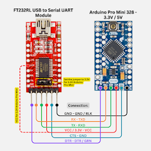
You can program an Arduino Pro Mini using an FT232RL USB to UART TTL converter. Before interfacing them, make sure your computer has the Virtual COM Port (VCP) Driver installed, which can be found on the FTDI website.

Follow this connection diagram to connect both devices appropriately, ensuring proper voltage levels. Finally, use the Arduino IDE to upload your code to the 3.3V/8MHz or 5V/16MHz Pro Mini.


No comments
If you have any doubts or questions, please let me know. Don't add links as it goes to spam. Share your valuable feedback. Thanks