When the current flowing through an inductive load, such as solenoids, motors, and transformers is suddenly interrupted, this stored energy seeks a path to dissipate. As a result, a high-voltage spike, known as a back electromotive force (EMF), is generated. This back EMF can have detrimental effects on the circuit, potentially damaging sensitive components or causing malfunctions.
This is where the flyback diode is connected in parallel to the inductive load, forming a path for the back EMF to safely dissipate. When the current is interrupted, the diode provides a low-resistance path, allowing the energy to circulate within the inductive load. That's why it's also referred to as a freewheeling diode. By doing so, the diode prevents the back EMF from reaching dangerous levels and protects the rest of the circuit from potential harm.

|
| The graph shows time versus input voltage and output voltage-current with and without using a flyback diode which illustrates the main purpose of using this essential passive component in a circuit. |
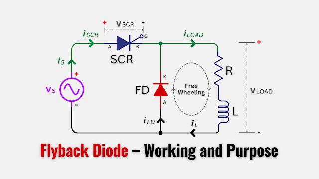
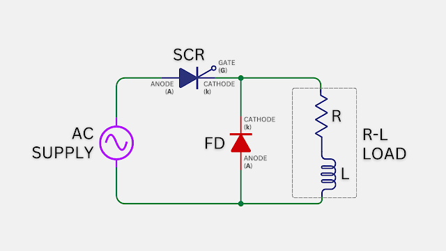
The working principle of freewheeling or flyback diode is relatively simple. The schematic of a half-wave controlled rectifier circuit using SCR is shown below. Where a flyback diode (FD) is connected in parallel to the R-L load in the circuit.

During normal operation, when the current is flowing through the inductive load, the diode (FD) is in a reverse-biased state, effectively blocking any current flow.

However, when the current is interrupted, the inductive load tries to maintain the flow by generating the back EMF.
This reverse biases the diode, causing it to become forward-biased and allowing the energy to circulate within the load. Once the back EMF dissipates, the diode returns to its reverse-biased state, ready for the next cycle.

This diode connection offers various electronic system applications advantages, ensuring their reliability and longevity. Protecting sensitive components from voltage spikes generated by inductive loads, such as the ignition coil. They also ensure a smooth transition during load changes, preventing voltage fluctuations. This configuration is commonly used in relay and switch circuits, where the interruption of current flow is frequent.


No comments
If you have any doubts or questions, please let me know. Don't add links as it goes to spam. Share your valuable feedback. Thanks